Homework 5 (Due October 14th)
Homework 5 (Due October 14th)
1. Gauss’ Law and Cavities
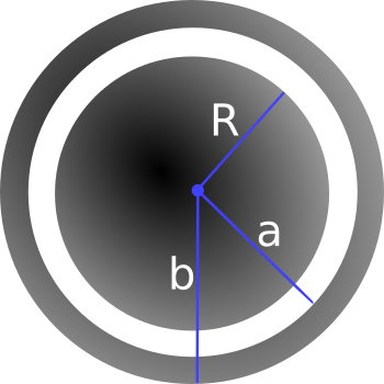
A metal sphere of radius $R$, carrying a charge $+q$, is surrounded by a thick concentric metal shell (inner radius $a$, outer radius $b$). The shell carries no net charge. Where requested, please explain your reasoning.

- Sketch the charge distribution everywhere. If the charge is zero anywhere, indicate that explicitly.
- From part 1, you probably noticed the charge distributes in some way on the metals. Determine the surface charge density $\sigma$ at $R$, at $a$, and at $b$.
- Sketch the electric field everywhere; explain how you know the field you have drawn is correct. If the field is zero anywhere, indicate that explicitly.
- Find the potential everywhere, use $r \rightarrow \infty$ as your reference point for $V=0$.
- Now the outer surface is touched by a grounding wire, which lowers its potential to zero. How do your answers change to parts 2 and 4? Explain your reasoning.
2. Coax capacitors
Consider a coaxial cable with an inner conducting cylinder has radius $a$ and the outer conducting cylindrical shell has inner radius $b$. It is physically easy to set up any fixed potential difference $\Delta V$ between the inner and outer conductors. In practice, the cable is always electrically neutral.
- Assuming charge per length $+\lambda$ and $-\lambda$ on the inner and outer cylinders, derive a formula for the voltage difference $\Delta V$ between the cylinders.
- Assuming infinitely long cylinders, find the energy stored per length (W/L) inside this capacitor. Notice we are asking for the energy per unit length, the answer is not infinity! Let’s do it two ways so we can check:
- Find the capacitance per length ($C/L$) of this system, and then use stored energy $W = \frac{1}{2} C (\Delta V)^2$.
- Integrate the energy density stored in the E field.
- Based on your answers to part 2, where in space would you say this energy is physically stored?
- Estimate the capacitance per meter of the coaxial cable that the cable company uses to send TV signals into homes. Justify any assumptions.
- This model is also excellent for “axons”, which are long cylindrical cells (basically coax cables) carrying nerve impulses in your body and brain. Estimate the capacitance (in SI metric units, Farads) of your sciatic nerve. Assumptions - the sciatic nerve is the longest in your body, it has a diameter of roughly 1 micron, and a length of perhaps 1 m. Note that axons generally have a value of b which is very close to a (i.e. the gap is extremely tiny, b-a is about 1 nanometer. ) so you can simplify your expression using $ln(1+\epsilon)\approx\epsilon$.
3. What is a farad?
- The farad is actually an enormous unit of capacitance. To illustrate this, treat the Earth as a conducting sphere and find its capacitance.
- Look up the capacitance of typical capacitors used in electronic applications. If these capacitors were conducting spheres, roughly how large would they be physically? Does this size seem to be the right size given your experience with electronic components?
4. Superposition in conductors (“shielding”)
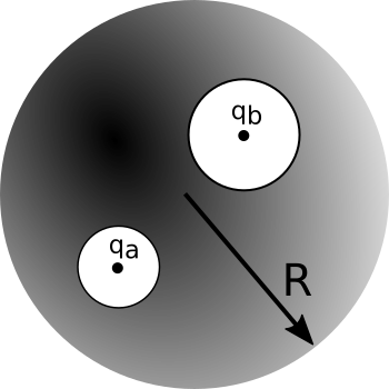
We carve out two spherical cavities from a metal sphere of radius $R$ (as shown below). The first cavity (radius, $a$) has a charge $+q_a$ placed at the center of the cavity. Similarly, the second cavity (radius, $b$) has a charge $+q_b$ placed at the center of that cavity.

- Sketch the surface charge everywhere. Explain how you know the surface charge looks this way.
- Determine the surface charges ($\sigma_a$, $\sigma_b$, and $\sigma_R$).
- Sketch the electric field everywhere. If the field is zero anywhere, indicate this explicitly. Explain how you know the electric field looks this way.
- Determine the magnitude of electric field outside the conductor and inside each cavity.
- If we brought an external charge $q_c$ near the conducting sphere how do your answers to parts 1-4 change? You may answer in words, pictures or both.
5. Proving Uniqueness
For this homework problem, you will prove the “second uniqueness theorem” yourself, using a slightly different method than what Griffiths does (though you may find some common “pieces” are involved!) It will really help to review/read the section on the second uniqueness theorem as you work through this problem.
Do it like this:
- Green’s Identity is true for ANY choice of T and U, so let the functions T and U in that identity both be the SAME function.
- Specifically, you should set them both equal to $V_3=V_1-V_2$ where $V_1$ and $V_2$ represent different solutions to the same boundary value problem ($\nabla^2 V = 0$ with boundary conditions).
- Then, using Green’s Identity (along with some arguments about what happens at the boundaries, rather like Griffith’s uses in his proof) should let you quickly show that $E_3$, which is defined to be the negative gradient of $V_3$ (as usual), must vanish everywhere throughout the volume. QED.
Work to understand the game. We are checking if there are two different potential functions, $V_1$ and $V_2$, each of which satisfies Laplace’s equation throughout the region we’re considering. You construct (define) $V_3$ to be the difference of these, and you prove that $V_3$ (or in this case, $\mathbf{E}_3$) must vanish everywhere in the region. This means there really is only one unique E-field throughout the region after all! This is another one of those “formal manipulation” problems, giving you a chance to practice with the divergence theorem and think about boundary conditions.
6. Potential and electric field with Laplace’s equation
In class we derived the solution for the 2D version of Laplace’s equation with the boundary conditions shown below.

That solution was analytic, but it contained an infinite series:
\[V(x,y) = \sum_{n=1,3,5,\dots}^{\infty} \dfrac{4 V_0}{\pi n} \sin \left(\dfrac{n\pi x}{a}\right)e^{-\dfrac{n\pi y}{a}}\]While perfectly analytic, this solution is hard to visualize. What does that solution look like? Take $V_0 = 10V$ and $a = 1m$.
- Plot the approximate solution in 3D space using Python’s
mplot3Dfor just the first term in the sum (i.e., only for $n = 1$). Download this Jupyter notebook (you can view it here), which walks you through how to plot in 3D. - Plot the approximate solution in 3D space for the first 5 terms. What do you notice about the boundary where $V=V_0$?
- Plot the approximate solution such that the boundary where $V=V_0$ looks very close to constant. How many terms did you need? If you didn’t do it for Part 2, you will have to figure out how to automatically compute each term to construct your plot instead of copying-and-pasting 50, or 100, or 1000 times!
- Given this plot of the potential, sketch (by hand) what the electric field looks like. Recall that $\mathbf{E} = -\nabla V$.
7. Potential in a cubical box
You have a cubical box (sides all of length $a$) made of 6 metal plates that are insulated from each other. The left wall is located at $x=-a/2$ and the right wall is at $x=+a/2$. Both left and right walls are held at constant potential $V=V_0$. All four other walls are grounded ($V=0$ for these walls).
(Note that we’ve set up the geometry so the cube runs from $y=0$ to $y=a$, and from $z=0$ to $z=a$, but from $x=-a/2$ to $x=+a/2$ This should actually make the math work out a little easier!)
- Find the potential $V(x,y,z)$ everywhere inside the box.
- Also, is V=0 at the center of this cube?
- Is E=0 there? Why, or why not?