Homework 11 (Due December 9th)
Homework 11 (Due December 9th)
1. Coordinate Free Dipole Equation
In class we derived the magnetic field formula for the magnetic moment of a pure dipole which points in the z direction, located at the origin:
\[\mathbf{B} = \dfrac{\mu_0 m}{4 \pi r^3}(2 \cos \theta\,\hat{r} + \sin \theta\,\hat{\theta})\]Here $\mathbf{m}=I\mathbf{a}$ ($\mathbf{a}$ is the area vector of our tiny dipole) But sometimes $\mathbf{m}$ points in another direction than just $z$-hat! A more elegant way to write B which does not explicitly depend on any choice of coordinate axes is:
\[\mathbf{B} = \dfrac{\mu_0}{4 \pi r^3}(3 (\mathbf{m}\cdot\hat{r})\hat{r} - \mathbf{m})\]- For this problem, assume the second equation above is correct, define your $z$-axis to lie along the direction of the magnetic moment $\mathbf{m}$, and show that this leads back to first equation.
Coordinate free formulas are nice, because now you can find B for more general situations!
2. Semi-classical electron dipole moment
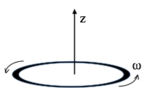
A thin uniform solid torus (a “donut”) has total charge $Q$, mass $M$, radius $R$. It rotates around its own central axis at angular frequency $\omega$, as shown.

- Find the magnetic dipole moment $m$ of this rotating donut. What are the SI units of dipole moment?
- Compute the ratio $m/L$, the “magnetic dipole moment” divided by the angular momentum. This is called the “gyromagnetic ratio”.
- What is the gyromagnetic ratio for a uniform spinning sphere? HINT: This question really doesn’t require any additional calculating: picture the sphere as a bunch of rings, and apply the result of part 2.
- In quantum mechanics, the angular momentum of a spinning electron is $\hbar/2$. Use your results above to deduce the electron’s magnetic dipole moment (in SI units.)
Note: This “semi-classical” calculation is low by a factor of almost exactly 2. Dirac developed a relativistic form of quantum mechanics which got the factor of 2 right in the 1930’s. In the ‘40’s, Feynman, Schwinger, and Tomonaga calculated tiny extra corrections arising from QED (Quantum electrodynamics) For fun, find the current best-value for the electron magnetic dipole moment. If you compare theory and measurement, you will be extremely impressed at the agreement (~12 digits!) It may make you “believe” in quantum physics in a way you might not have before! That’s not how it works in practice though- people use this measurement to extract a fundamental constant of nature, and then use that value to predict OTHER experiments.
3. Force between magnets
Toy magnets seem to have a force law which “turns on” quite suddenly as they approach, it doesn’t really feel like a $1/r^2$ force. That’s because it is not!

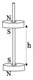
- Consider two small magnets (treat them as point-like perfect dipoles with magnetic moments $m_1$ and $m_2$, to keep life as simple as possible). In the configuration shown above (“opposite poles facing”), find the force between them as a function of distance r. (Does the sign work out for you sensibly?)
- Let’s do a crude estimate of the strength of the magnetic moment of a simple cheap magnet. Assume the atomic dipole moment of an iron atom is due to an (unpaired) electron spin. Question 2 above taught us what the magnetic dipole moment of a single electron is (or, just look it up to get the factor of 2 right!) The mass density and atomic mass of iron are also easy to look up. Consider a small, ordinary, kitchen fridge “button sized” magnet, and make a very rough estimate of its total magnetic moment.
- Use your formula from part 1 to estimate how high ($h$) one such magnet would “float” above another (if oriented as shown below).
- Does your answer seem at all realistic, based on your experiences with small magnets? (note that such a configuration is not stable - why not? I’ve seen toys like this, but they have a thin wooden peg to keep the magnets vertically aligned, that’s how I drew it in the figure).

4. Bound Currents I
Consider a long magnetic rod, radius $a$. Imagine that we have set up a permanent magnetization $\mathbf{M}(s,\phi,z) = c \hat{z}$, with $c$ = constant. Neglect end effects, assume the cylinder is infinitely long.
- Calculate the bound currents $\mathbf{K}_b$ and $\mathbf{J}_b$ (on the surface, and interior of the rod respectively).
- What are the units of $c$?
- Use these bound currents to find the magnetic field inside and outside the cylinder. (Direction and magnitude)
- Find the $\mathbf{H}$ field inside and outside the cylinder, and verify that $\oint \mathbf{H} \cdot d\mathbf{l} = I_{free}$ works. Explain briefly in words why your answer might be what it is.
- Now relax the assumption that it is infinite - if this cylinder was finite in length ($L$), what changes? Sketch the magnetic field (inside and out). Briefly but clearly explain your reasoning. Please draw two such sketches, one for the case that the length $L$ is a few times bigger than a (long-ish rod, like a magnet you might play with from a toy set), and another for the case $L \ll a$, which is more like a magnetic disk than a rod.
5. Bound Currents II
Like the last question, consider a long magnetic rod, radius $a$. This time imagine that we can set up a permanent azimuthal magnetization $\mathbf{M}(s,\phi,z) = c s \hat{\phi}$, with $c$ = constant, and $s$ is the usual cylindrical radial coordinate. Neglect end effects, assume the cylinder is infinitely long.
- Calculate the bound currents $\mathbf{K}_b$ and $\mathbf{J}_b$ (on the surface, and interior of the rod respectively).
- What are the units of $c$?
- Use these bound currents to find the magnetic field $\mathbf{B}$, and also the $\mathbf{H}$ field, inside and outside. (Direction and magnitude)
6. Bound Currents III
Once more, consider a very long cylinder (radius $R$) with a permanent magnetization, this time again parallel to the axis: $\mathbf{M} = c s \hat{z}$, (where $c$ is a constant, and $s$ is the usual distance from the cylinder’s axis). There is no free current anywhere.
- Find the magnetic field inside and outside the cylinder by figuring out the bound current everywhere and then figure out $\mathbf{B}$ created by those.
- Let’s find the $\mathbf{B}$ field inside and outside another way! This time, use Ampere’s law in the form: $\oint \mathbf{H} \cdot d\mathbf{l} = I_{free}$, and then use the standard relation, $\mathbf{H} = \frac{1}{\mu_0}\mathbf{B} - \mathbf{M}$, to get $\mathbf{B}$. (It should agree with part 1)